Cloud Foundry for Healthcare: Addressing Networking and Portability

Earlier this year, we wrote about building a highly available and mission-critical architecture with Cloud Foundry—implemented for a manufacturer of healthcare devices. The system is processing medical data collected from 1.5+ million patients across dozens of healthcare organizations.
Here, we further elaborate on the details of this Cloud Foundry–based healthcare system, focusing on addressing various networking/security challenges and providing portability between OpenStack and AWS.
Specific requirements
Sergey Sverchkov
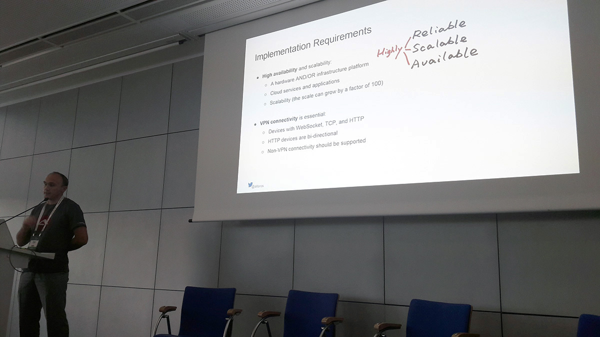
In his session at Cloud Foundry Summit in Frankfurt, Sergey Sverchkov (Software Architect, Altoros) discussed specific requirements for the project.
Previously, the IoT system described in this post was supplied by the manufacturer with a hardware server—with no scalability or fault tolerance. There are still hundreds of such installations in various healthcare organizations. The only way to maintain the product was to send an engineer to each customer location, which led to enormous amount of maintenance work. So, the idea was to move the software to the cloud and eliminate most of the routine support activities for local on-site installations.
To achieve the goal, the team needed to enable:
- Portability of the platform between OpenStack (running on the hardware) and a public cloud provider like AWS
- VPN connectivity as the primary mode of accessing the cloud to ensure security
Option #1. An IoT platform on OpenStack
To achieve high availability of the OpenStack deployment, three physical nodes (or blades) were allocated to OpenStack management components. OpenStack compute services responsible for running virtual machines were distributed across three availability zones. Each availability zone represented a group of three or more physical nodes.
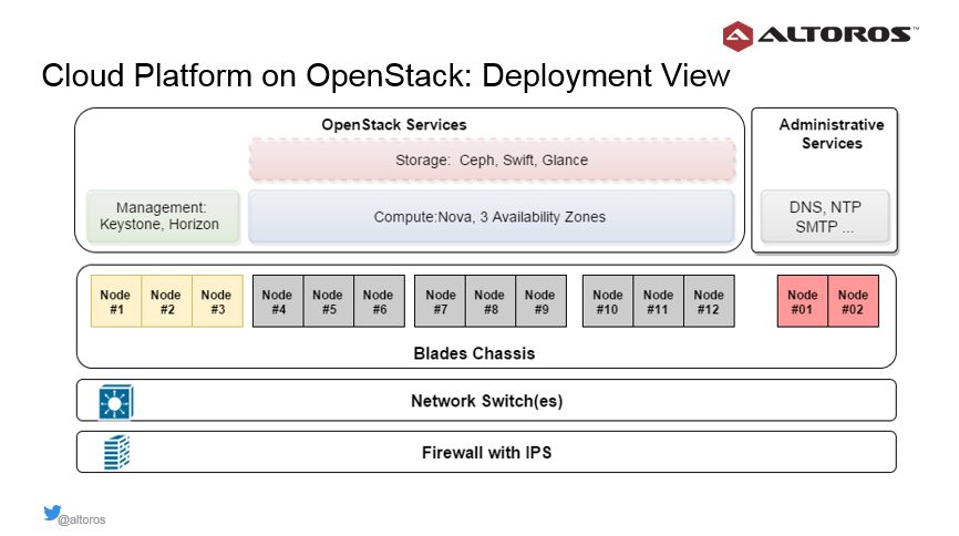
“This creates redundancy for virtual machines launched by OpenStack. It also allows us to distribute virtual machines evenly in each availability zone.” —Sergey Sverchkov, Altoros
“This approach to deployment means that we can scale OpenStack’s computing and storage capacity simply by adding new blades or chassis,” he added.
Network model for the OpenStack deployment
To secure the private cloud, the Cisco ASA 5545 hardware was used as a firewall for the OpenStack deployment. It supports:
- More than 2,000 concurrent VPN tunnels with a total bandwidth of 400 Mbit/s
- Up to 300 VLANs
- Site-to-site and personalized administrative VPN connections
The Cisco hardware can be also clustered in the Active-Standby mode to achieve high availability on the firewall level.
Here are some examples of network configuration:
- Administrative network 10.30.0.0/24, native VLAN
- “Public” cloud network 172.30.0.0/24, VLAN 101
- OpenStack management network 192.168.100.0/24, VLAN 102
- OpenStack storage network 192.168.200.0/24, VLAN 103
- Networks for VMs 192.168.[111-120].0/24, VLAN 110-120
The administrative network is used to connect to the management interfaces of the physical nodes, firewall, and switch and configure the hardware remotely. The “public” cloud network is the network exposed to clients that access the cloud through VPN. There are also two internal OpenStack networks for storage and management traffic, as well as six subnets for the virtual machines.
Cisco ASA monitors access and routing between the administrative and “public” networks.
“Also, Cisco ASA controls what VPN can access what network, and even specific addresses. This means that for site-to-site connectivity from the customer network, we expose only the addresses of services that should be available to the customer.” —Sergey Sverchkov, Altoros
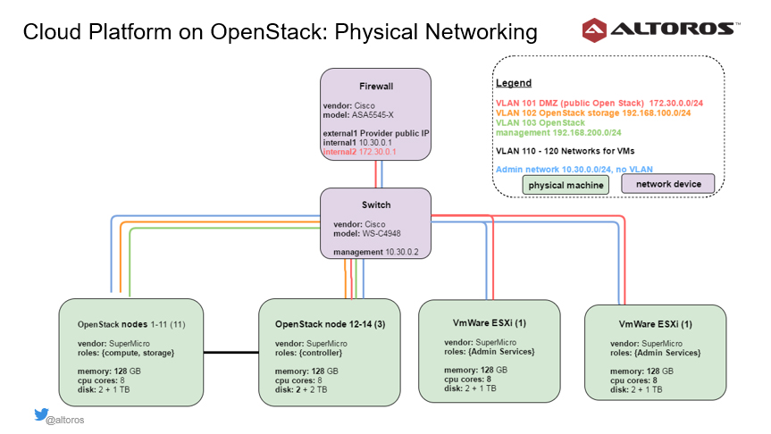
The firewall has one external and two internal interfaces. The external interface is configured with a public IP address provided by the data center. Two internal interfaces represent the administrative and “public” networks.
In our case, the firewall monitors traffic from the outside world to the cloud. It also controls how any service or virtual machine can connect to the Internet.
The Cisco switch has an address in the management network. All virtual LANs are also configured on the switch to provide communication between OpenStack nodes and virtual machines.
VPN model for the OpenStack deployment
For connecting to the private OpenStack cloud, a single VPN endpoint was provided. There are also two main types of VPN: personal VPN accounts for administrators and site-to-site connections between networks.
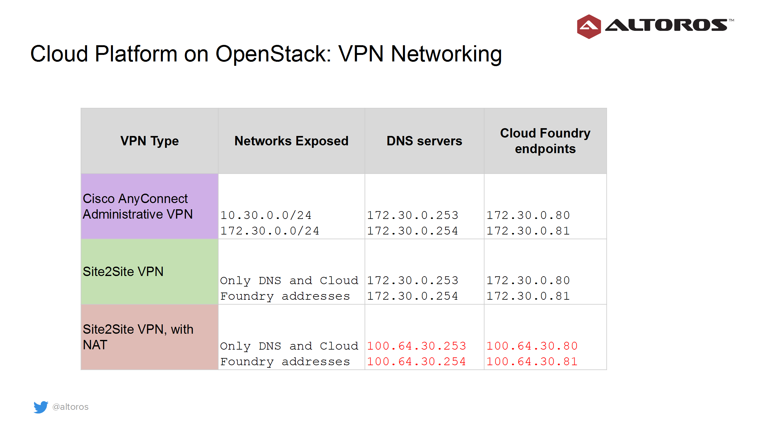
The summary of other cloud resources is given in the table below.
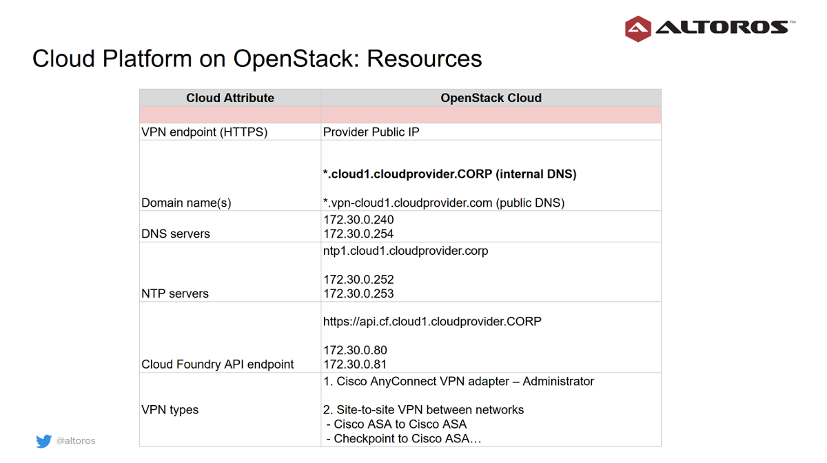
The main domain is private—for example, cloud1.cloudprovider.corp, where cloud1 is the designator of the cloud location or region, and cloudprovider.corp serves as an internal domain.
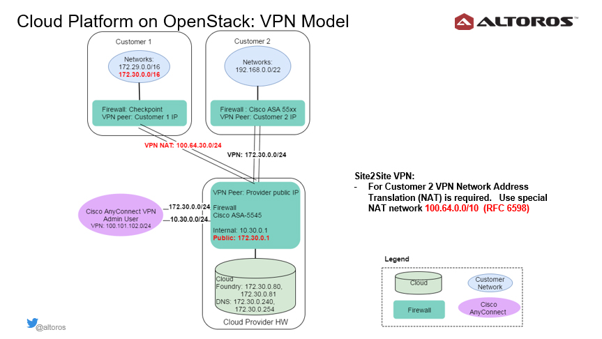
In the case of the Cisco AnyConnect VPN connection, which is represented by the purple circle in the image above, both the internal and “public” networks of the cloud are exposed to administrators. It allows them to manage and configure the physical nodes, network switches, firewall, and OpenStack deployment remotely.
Should there be any network overlaps in customer connections, the system utilizes the Network Address Translation (NAT) technology, using a special network range defined by RFC 6598.
While administrators can access the two cloud networks without restriction, site-to-site VPN connections get access only to DNS servers and Cloud Foundry endpoints.
DNS resolution, domains, and routes
For resolving domain names, two approaches were designed:
- Configuring DNS zone forwarding to DNS servers in the cloud:
- Set up DNS zone forwarding in a customer network
Zone: *.cloud1.cloudprovider.corp
– no NAT
DNS servers: 172.30.0.253, 172.30.0.254
– with NAT
DNS servers: 100.64.30.253, 100.64.30.254
- Set up DNS zone forwarding in a customer network
- Using public DNS records for resolving private IP addresses:
- Create A-records at a public domain owned by the health cloud provider (subdomains)
Name: *.vpn-cloud1.cloudprovider.com
Addresses: 100.64.30.80, 100.65.30.81
- Create A-records at a public domain owned by the health cloud provider (subdomains)
To support private and public domains for applications in Cloud Foundry, it is necessary to register shared domains and then include additional routes.
Create shared domain(s):
123456$ cf domainsGetting domains in as admin...name status typecf.cloud1.cloudprovider.corp sharedvpn-cloud1.cloudprovider.com sharedtcp-cf.cloud1.cloudprovider.corp shared tcpMap additional route(s) to an application:
1$cf map-route deviceserver vpn-cloud1.cloudprovider.com --hostname deviceserver
In our example, the main domain in Cloud Foundry was cf.cloud1.cloudprovider.corp, and we created an additional domain—vpn-cloud1.cloudprovider.com—for a public resolution process.
Device connectivity to the OpenStack cloud
Devices that communicate with the cloud were using the WebSocket, TCP, and HTTP protocols. The diagram below demonstrates two customer networks with overlapping ranges. To expose the cloud services, it was important to set up NAT rules.
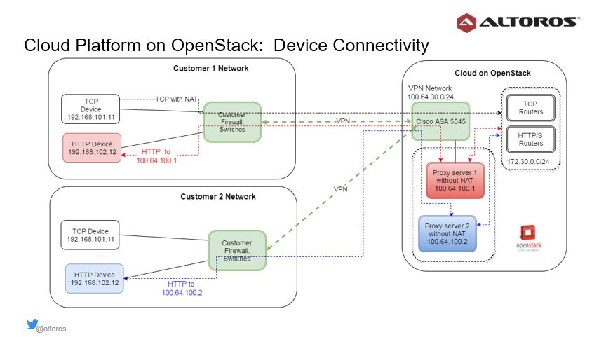
Devices that communicate via TCP and WebSocket establish persistent connectivity. The Cisco firewall supports hundreds of thousands of such connections and encryption bandwidth of up to 400 Mbit per second.
The TCP routers are used to connect TCP devices, and regular Cloud Foundry routers maintain connections of devices with the WebSocket protocol. So, these devices pose no issues: one just needs to adjust router settings (the number of open files and sockets, types of VM instances, etc.).
Still, some legacy HTTP devices may use a mode when a server can initiate an HTTP request to the device. With two remote networks (as shown in the image above), there are two HTTP devices that have the same internal network address. Cisco ASA cannot route such requests without knowing which VPN to use.
To solve this problem, proxy servers are allocated inside the cloud within the network range 100.64.100.0/24. Each combination of a proxy VM, VPN connection, and HTTP device in the customer’s network should be unique.
In this particular case, the Cisco firewall routes requests through the correct VPN. The routing table in Cisco ASA is virtual. It is updated on sending HTTP requests back and forth. This unique yet simple implementation approach is based on the standard IPv4 protocol and does not use expensive networking hardware with a customized TCP stack (for example, Cisco application-centric infrastructure).
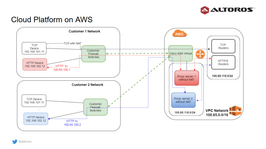
Option #2. An IoT platform on AWS
The next step was to enable the porting of the implementation from OpenStack to AWS. For the AWS deployment, a virtual private cloud (VPC) was used. Similar to OpenStack, network overlaps were handled by using a separate VPC network from the NAT range.
Since Amazon’s native VPN Gateway was not able to support all the required settings for healthcare use cases, Cisco ASA was brought into the mix as a virtual firewall. Its implementation functions similarly to that of a hardware firewall. So, the team just had to adapt their implementation of the OpenStack deployment to provide device connectivity. This proves that the designed architecture can be fairly easily moved between AWS and OpenStack infrastructures.
When building such a complex, portable cloud platform, an organization have to take care of many things. Private networks routing, encrypting and storing customer data separately, and running the pool of shared applications for customer multitenancy in Cloud Foundry are only some examples of the problems to be solved.
Of course, in case of AWS, we don’t have to worry about physical servers, network switches, routers, and redundant power supplies. But it is a quite common situation when Amazon notifies us about a virtual machine being decommissioned and we need to recreate it without downtime to the system.
For sure, tackling all these aspects has its challenges. However, with a well-thought-out system design and right tools, the goal is achievable. In return, you get something very important: control over deployment, security, as well as more flexibility in meeting specific regional/local requirements.
Want details? Watch the video!
Table of contents
|
Related slides
Further reading
- Building Scaled-Down, HA, Mission-Critical Architecture with Cloud Foundry
- Bringing Healthcare Home with the IoT
- IoT in Healthcare: “The Internet of Caring Things”
- GE Predix and the DDS Standard Transform Healthcare, Control Robots
About the expert